For some time I have contemplated using some sort of cooling mechanism to give me prefect fermentation temperatures while I ferment my beer. Last summer I painstakingly used my chest freezer kegerator. It was a horrible process. It involved removing one (or two) kegs, cranking up the temperature and lifting and setting the heavy bucket with 5 gallons of wort into the chest freezer.
Now that spring has sprung, and summer is within reach, it seemed like a great time to look into my options for a fermentation chamber. Another factor was my last 2 batches of beer had off-flavors form the yeast from fermenting too warm. I was determined to not brew again until I had a more reliable way of controlling the temperature of my fermenting wort.
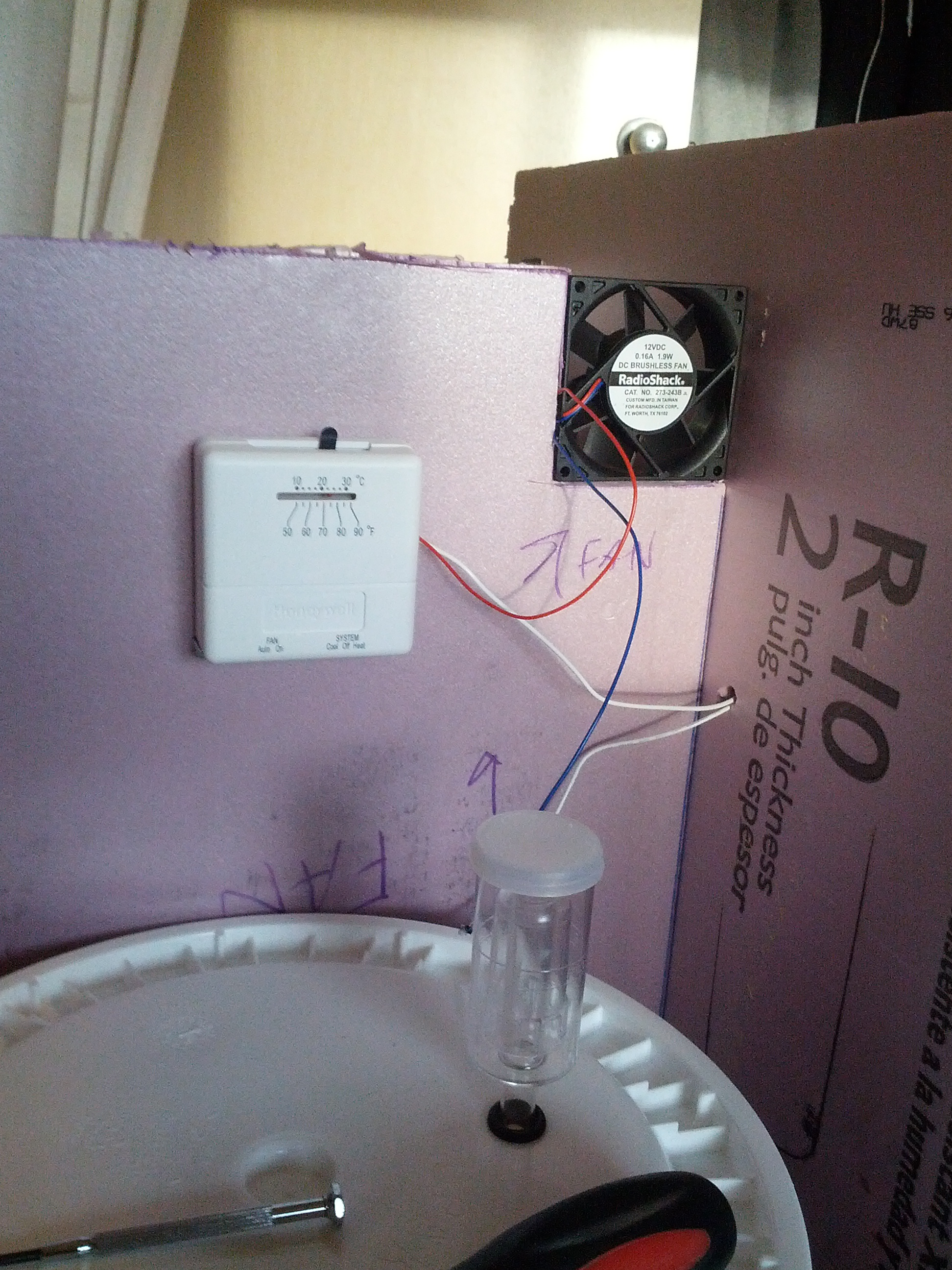
I ended up creating a Son of a Fermentation Chamber utilizing the instructions provided here. Essentially how it works is you build a chamber out of polystyrene foam board, which has great insulation qualities, and using a thermostat, a fan, and some frozen jugs you circulate cold air when the thermostat kicks on to cool your fermenter. The actual PDF linked in this paragraph has a much better explanation, so I encourage you to read it.
I like to do a ton of research before starting any project. I was able to find almost all the required parts at my local home depot (minus the computer fan and DC adapter). I couldn’t find a site or blog that had extremely detailed instructions with pictures, so I made sure to document each step in my process.
Here is a list of items I used:
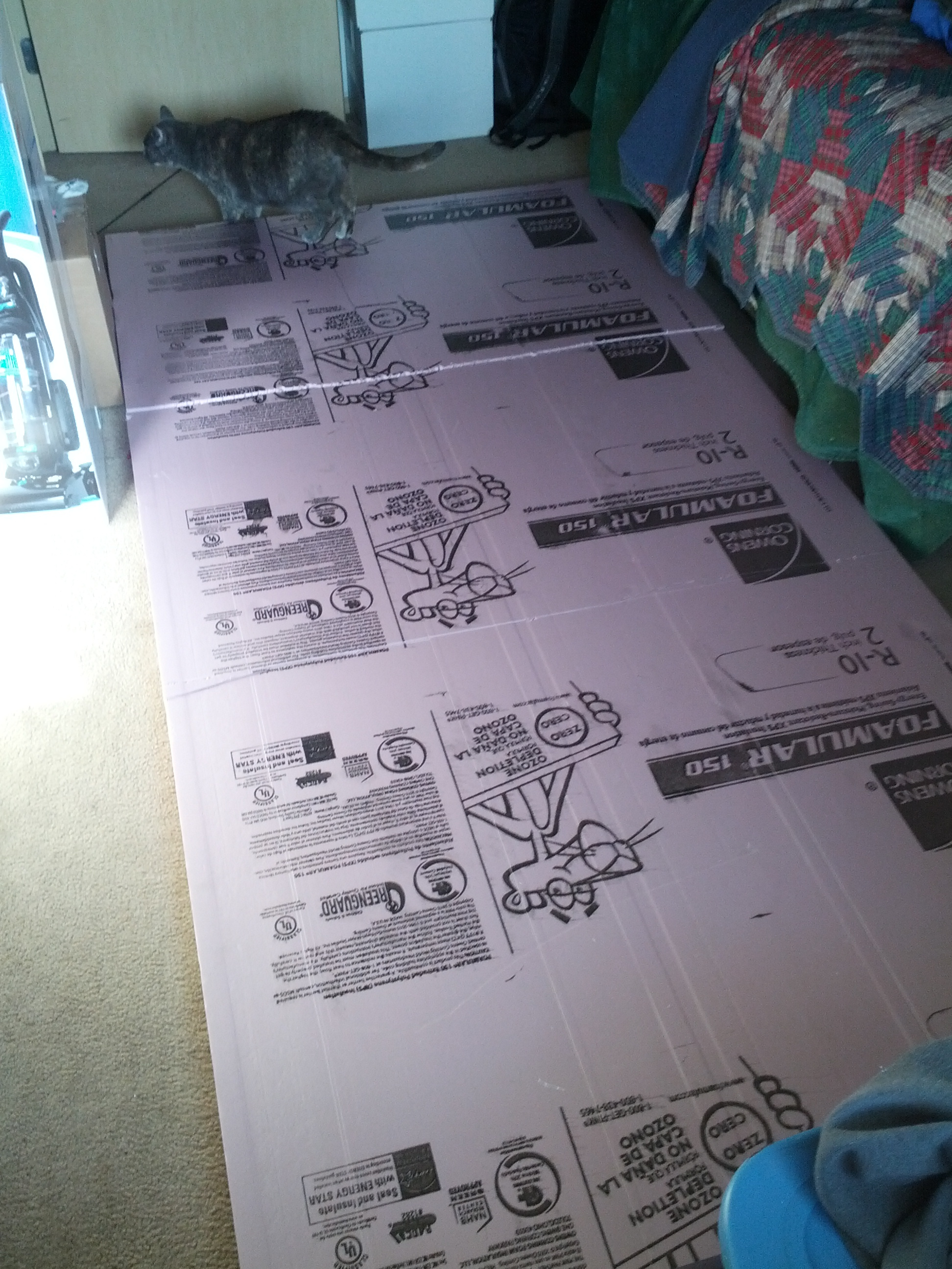
- 4ft x 8ft x 2in thick polystyrene foam board
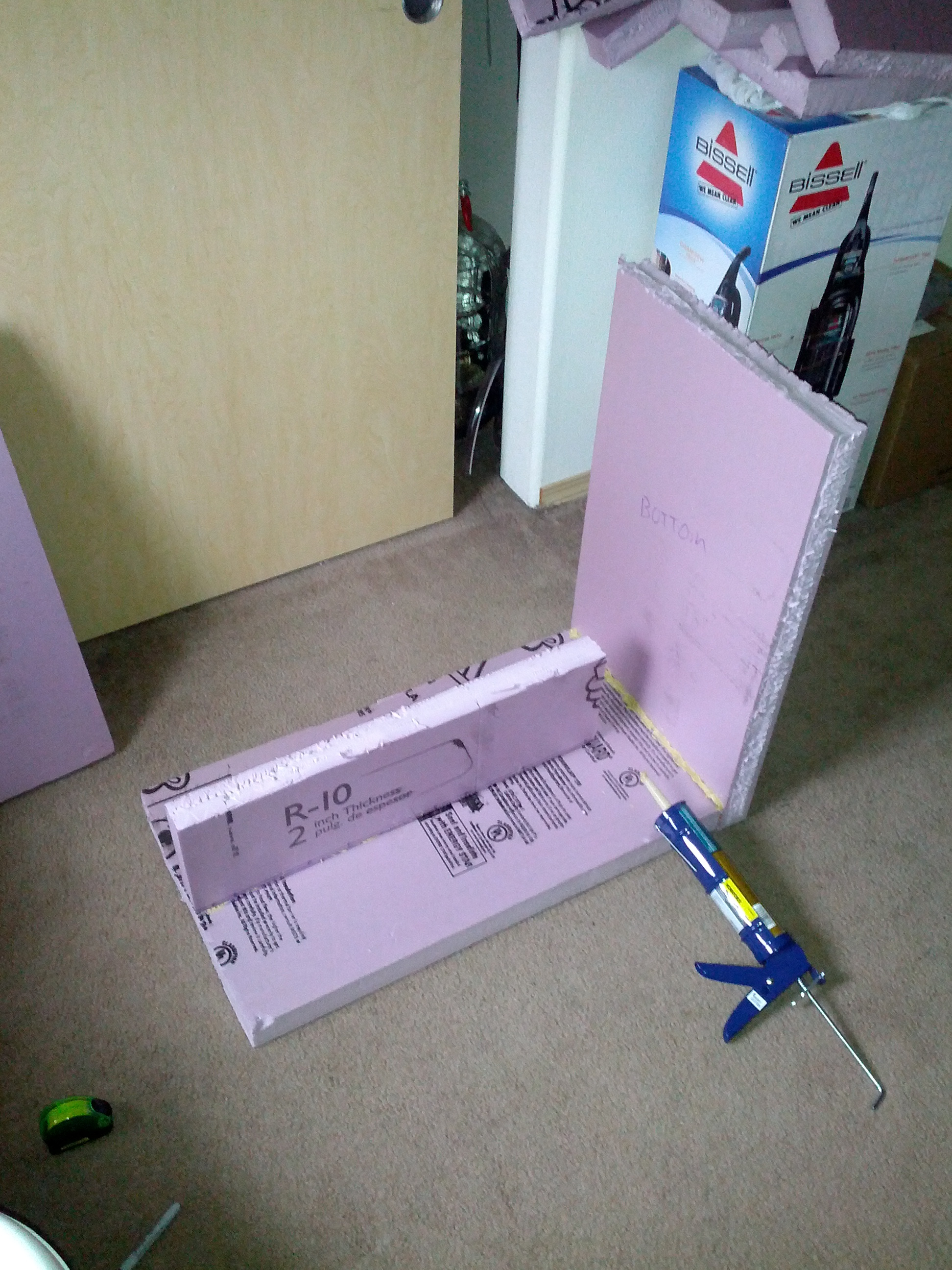
- Caulk gun and Liquid Nails
- 12 volt DC Computer Fan (Radio Shack model 273-243B)
- Enercell AC Adapter 1.5 – 12 volt (Radio Shack model 273-315)
- Honeywell Thermostat from Home Depot (Model # CT31A)
- 4 pieces of 1/4 inch square molding
- 1/4 inch Foam Tap Weatherstrip
I have a mid-size car and the foam board was way too big to fit in my vehicle. I thought I might be able to bring the drawing of the cuts and have an employee do them for me in the store. This is not the case. They will give you a utility knife and you can do the cutting, but that’s about it. So I crudely cut the foam board into 3 pieces by scoring each side in a semi-straight line and breaking the board.
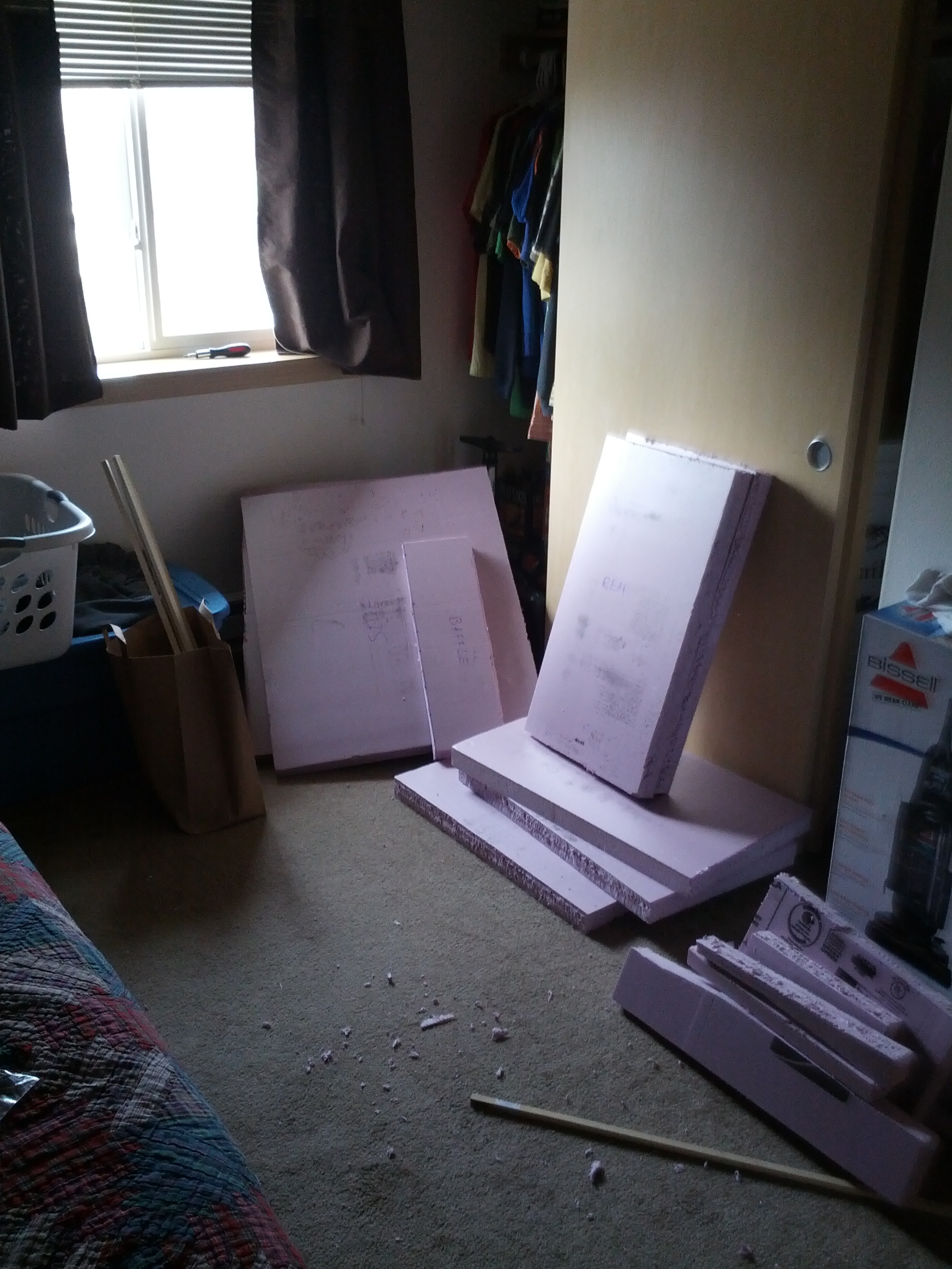
I don’t have many tools at home, and certainly didn’t have anything worthy enough to do straight and clean cuts for the polystyrene foam board. I measured and drew the lines, and then used a utility knife to do all the cuts. Again, I scored each side, and then roke the board to create the pieces. This resulted in many non-straight and non-flat surfaces. Despite the crappy cuts, I ended up with a working product. So, even if you don’t have the right tools, you can still make this work. I should also mention that when cutting the foam board, it’s extremely messy. I had to do all of mine in my bedroom. It is a much better job for a garage.
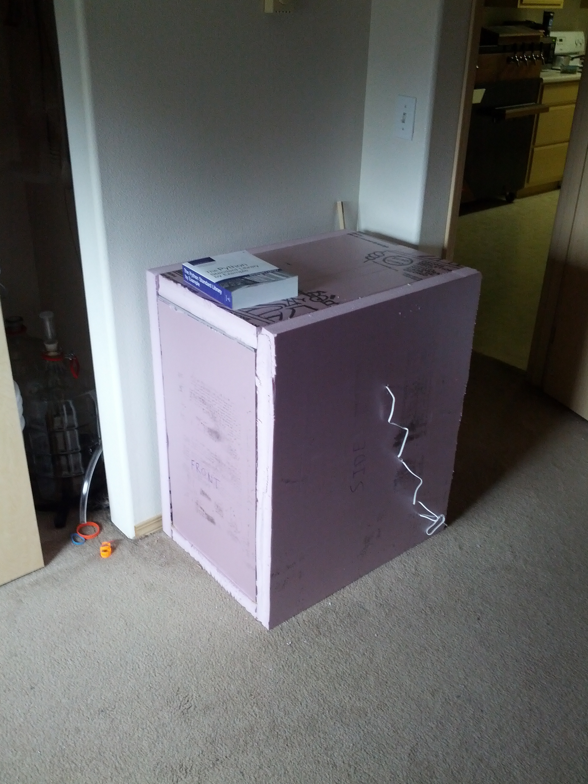
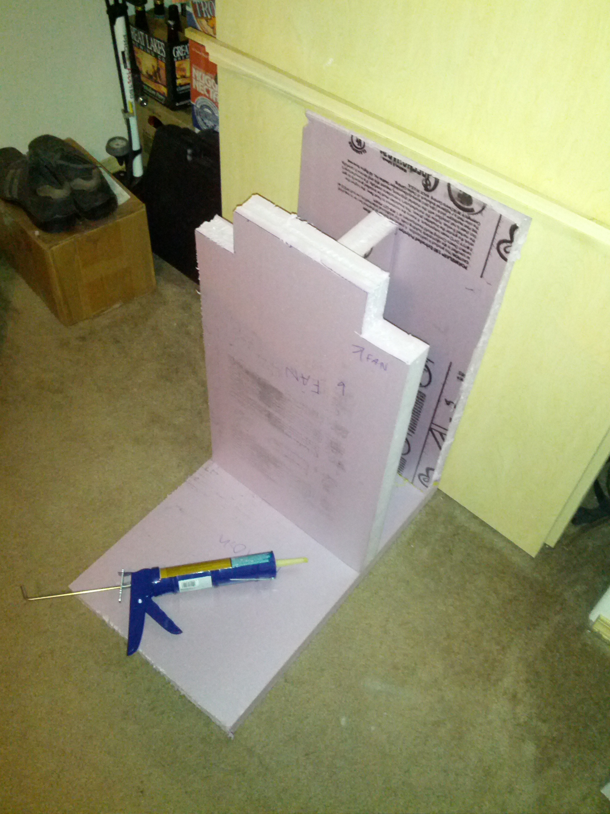
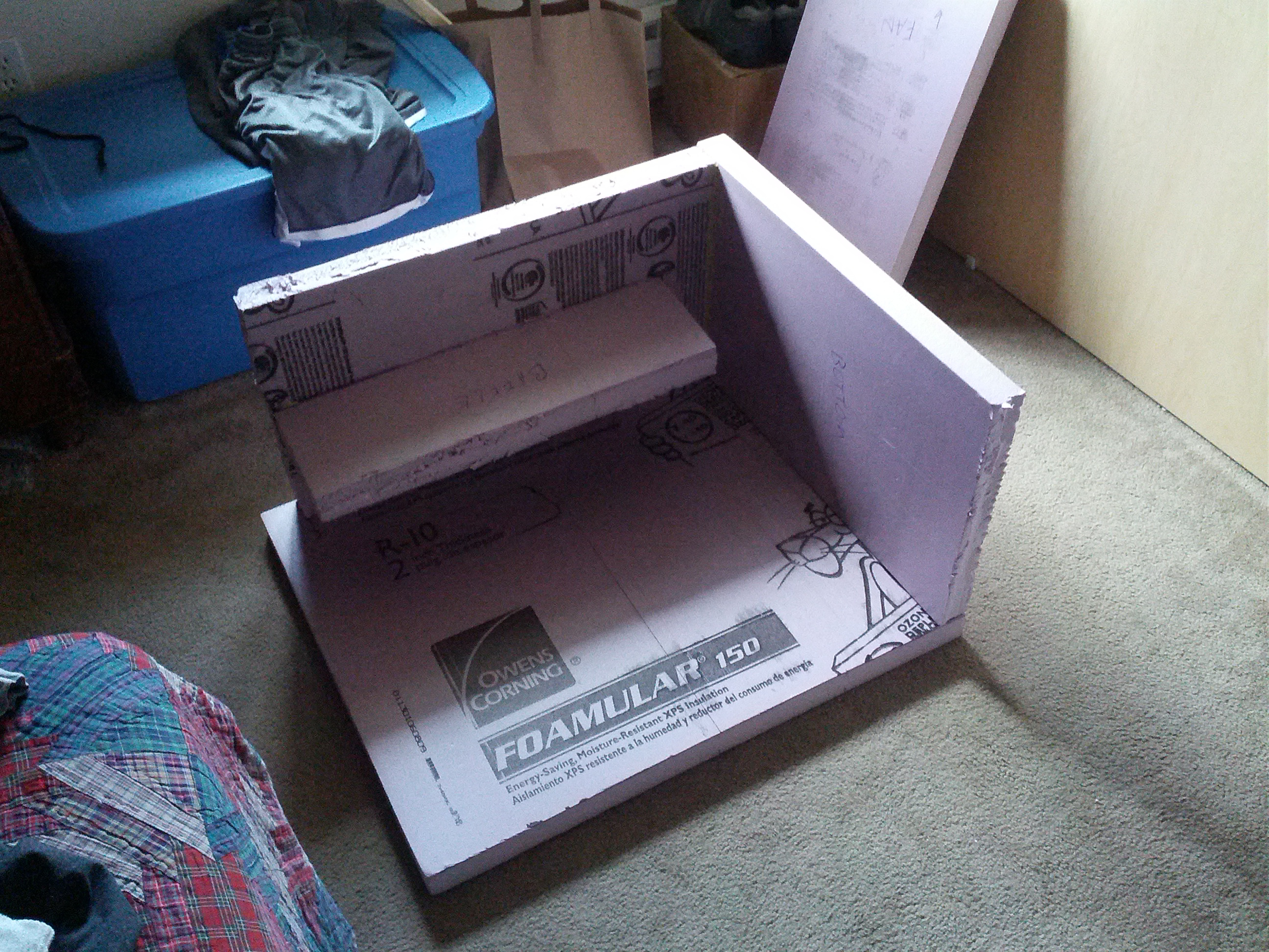
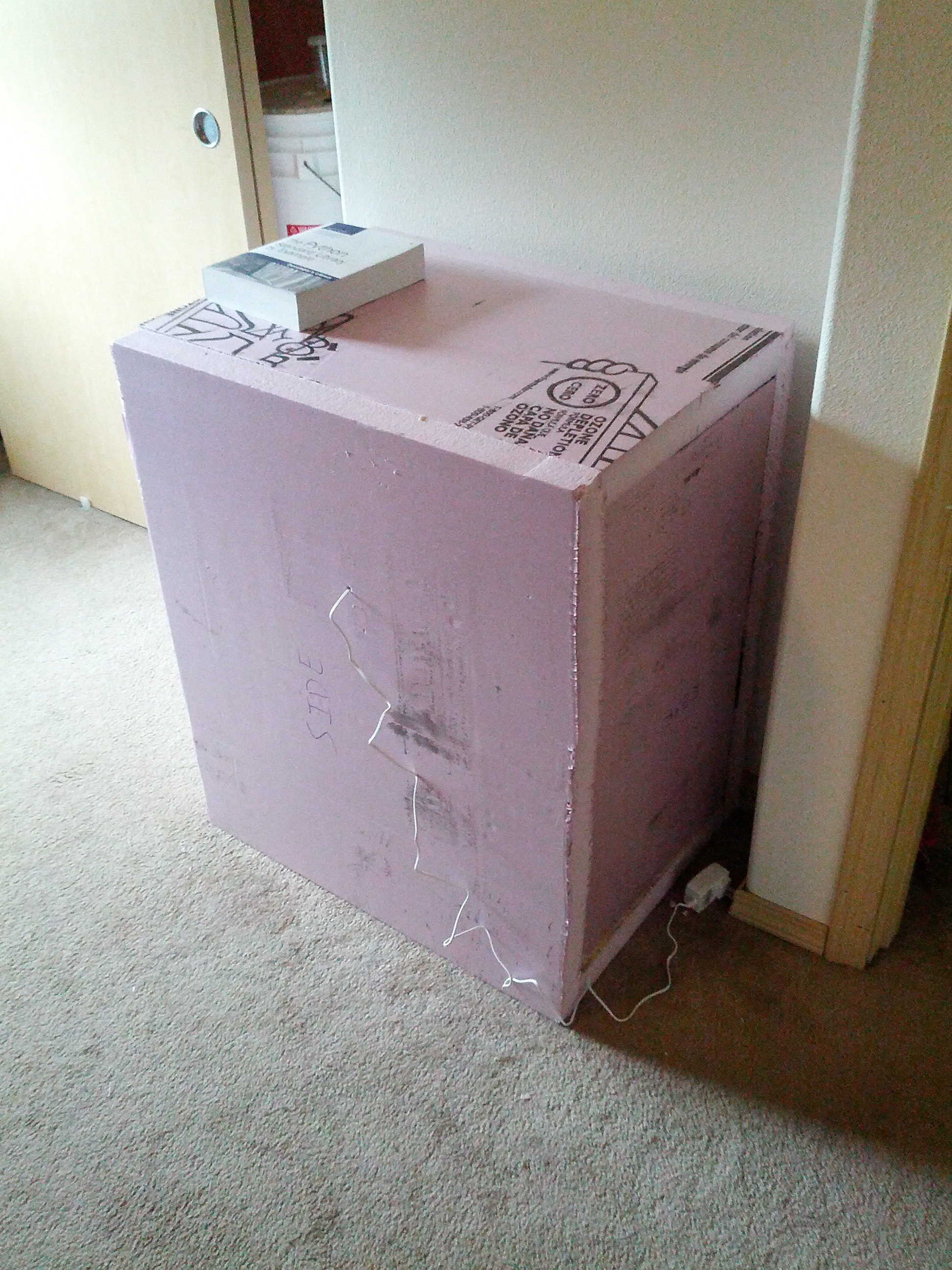
I used liquid nails as both an adhesive and a caulk. I began by gluing together the bottom and back. I then attached the baffle to the back followed by the “middle” piece to the bottom and baffle (consult the photo gallery for a better picture). Finally I attached the sides. The front and top panel are removable so you can get your fementer and frozen containers inside.
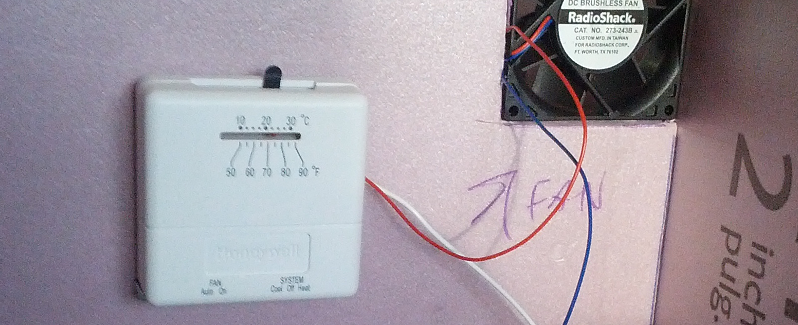
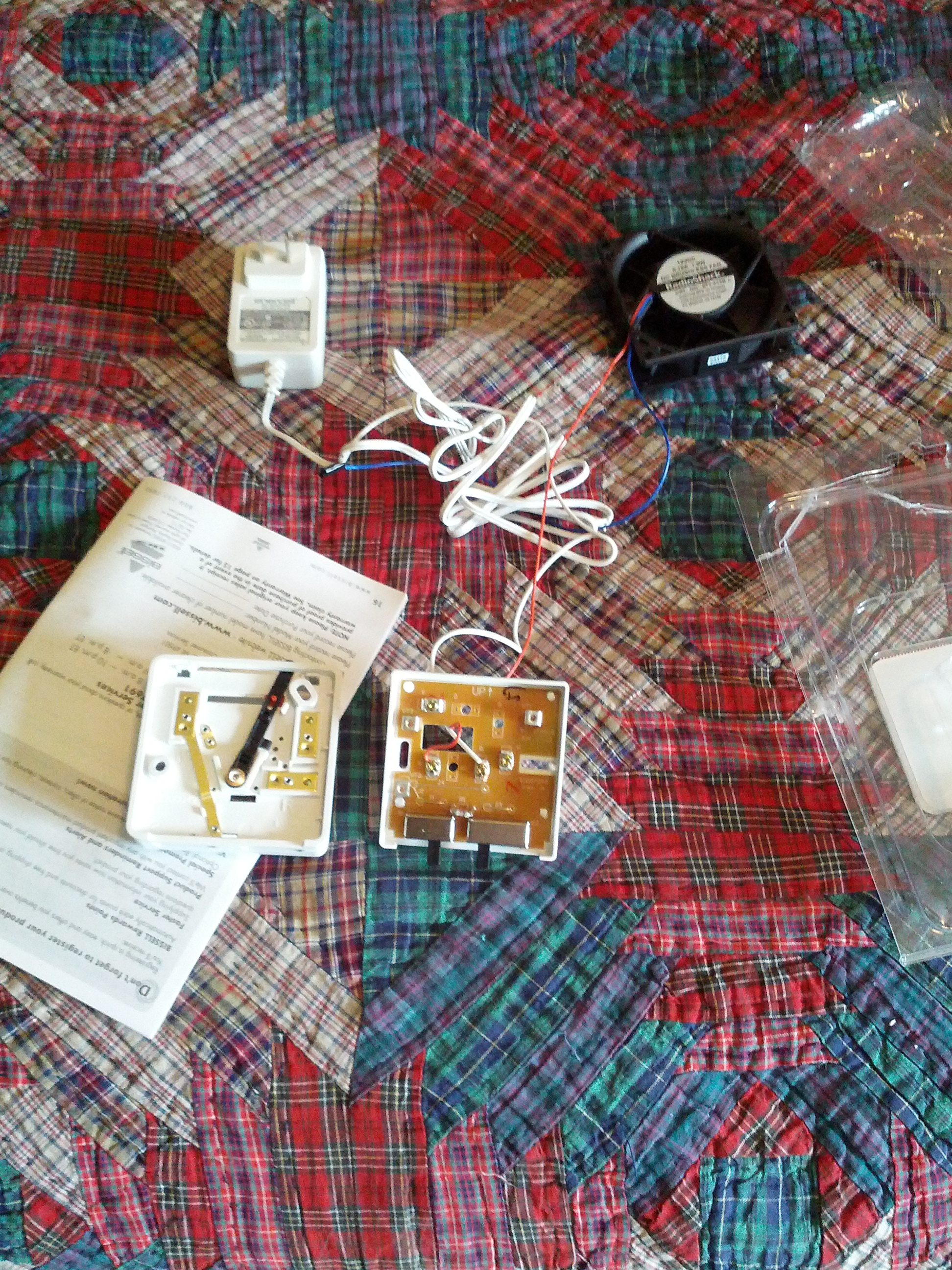
The next step for me was wiring up the thermostat and fan. I am by no means an electrician, so this was the part that concerned me the most. Especially because I couldn’t find the exact model of the thermostat that everyone else was using. There also weren’t many great diagrams and photos of the actual wiring. I almost bought a different thermostat that I found a tutorial for elsewhere, but ended up trying the original one I bought at Home Depot first. It turns out that it isn’t quite as challenging as I thought it would be. It took some trial and error but I was able to get it working.
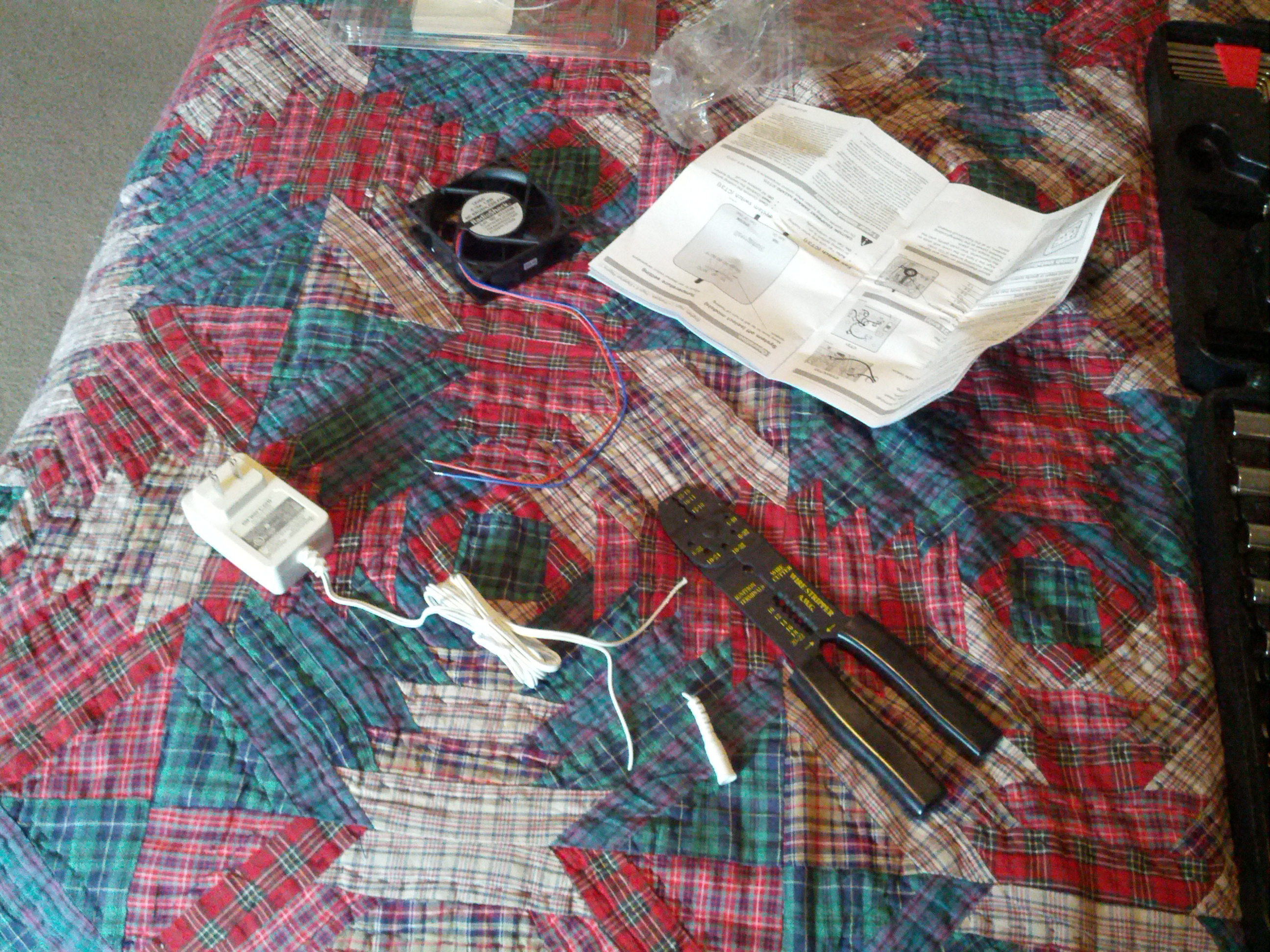
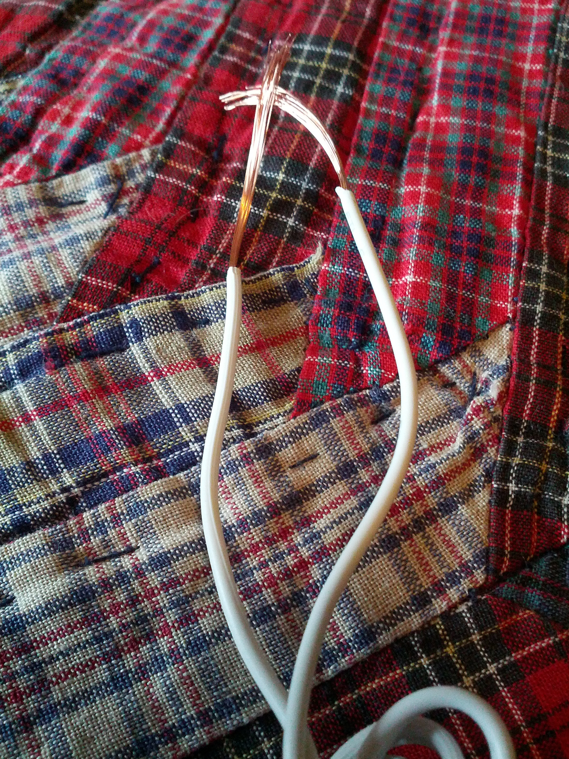
Fortunately I already owned the basic tools I needed to cut and strip the wires. The tool is pictured to the right. The first thing I did was cut the end off of the DC adapter. I then peeled apart the two wires and stripped off about 1/2″ off the end so the bare wire was exposed. The 2 wires from the DC adapter were not labeled as positive and negative, but after consulting the Internet, the one with a stripe on it is typically the positive wire. If there are colors, red is positive and black or blue is negative.
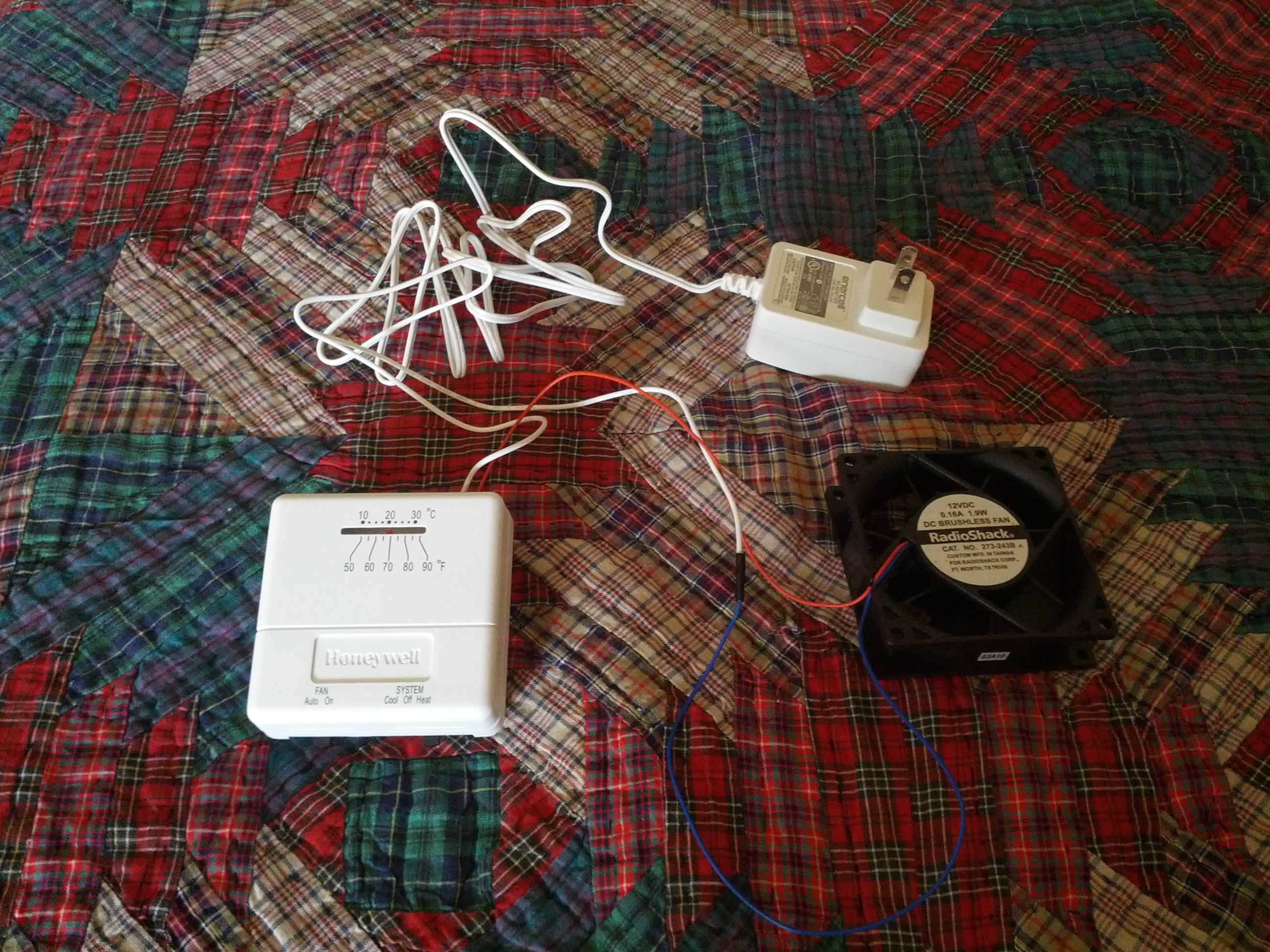
So I took the negative end of the DC adapter and twisted the wires together from it and the negative wire of the fan. The fan’s negative wire was blue in my case. I then put some electrical tape over it. It’s more reliable to soder the wires or put a plastic end over them and crimp it, but for testing purposes the electrical tape worked fine.
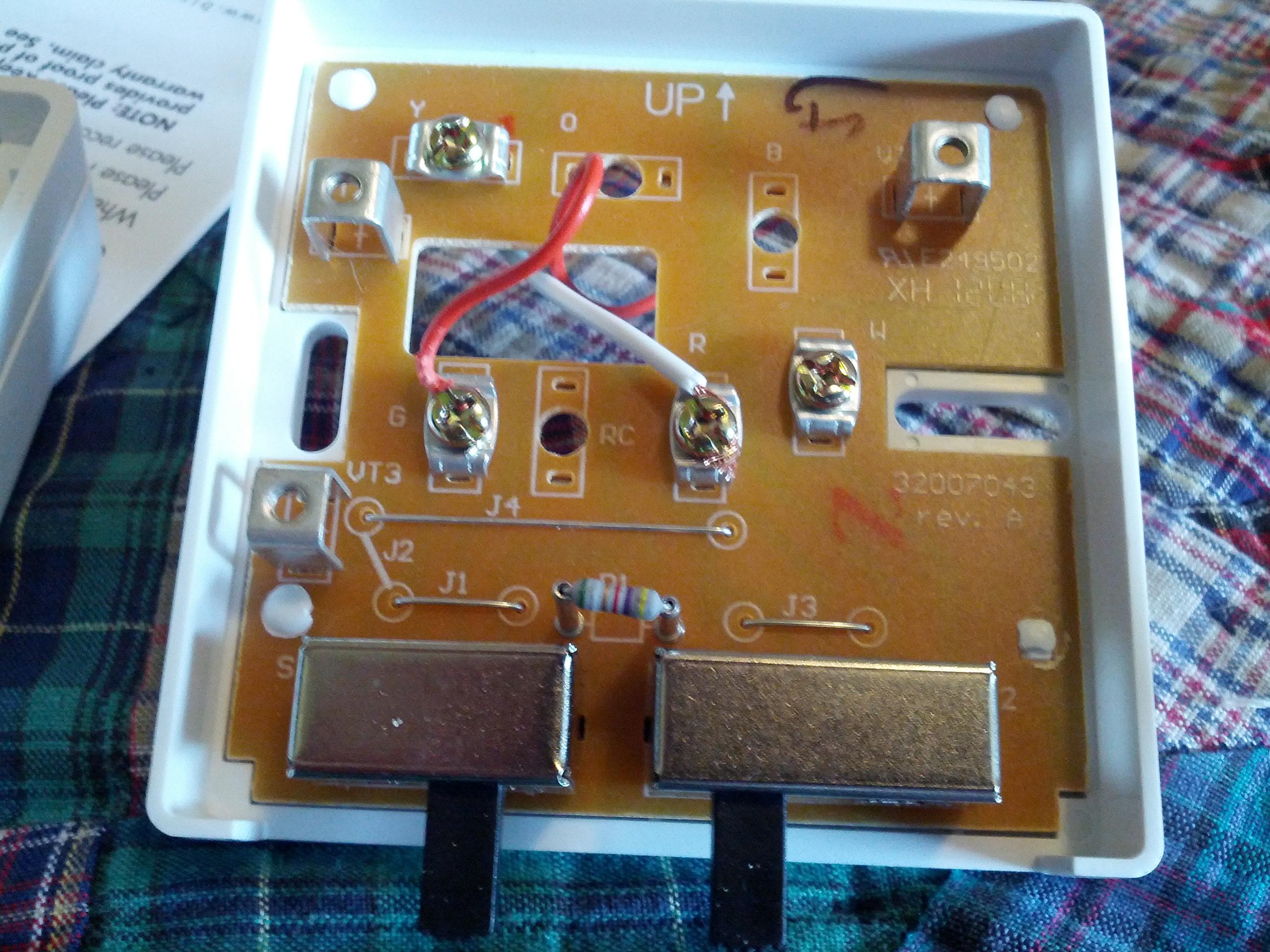
The positive end of the DC adapter went to the R terminal of the thermostat. For this I simply unscrewed the screw at the R terminal then wrapped the positive wire from the DC adapter around the screw and screwed it back down. Finally I took the positive wire from the fan (red) and wrapped it around the screw at the G terminal of the thermostat. The G terminal controls the fan on the thermostat.
The first 2 times I tried to plug it in and test it, it didn’t work. The first time was because on the piece of the thermostat under the face there was a plastic piece that needed to be removed. If I had just read the instructions carefully I would have caught that. The plastic piece also states clearly on the top to remove before operation. However, after removing that it still didn’t work. The fan would turn half a rotation then stop. It turns out that the DC adapter had a switch on the front of it to switch the voltage from 1.5 up to 12. After moving the switch to 12 volts the fan worked perfectly. Switching the thermostat to fan toggle to “On” caused the fan to run at all times, and switching it to “Auto” made the fan kick on/off when the temperature set on the thermostat was exceeded or met. So to recap the positive wire from the DC adapter connects to the R terminal of the thermostat to power it. The negative wire from the DC adapter connects to the negative wire of the fan. The positive wire of the fan then connects to the G terminal of the thermostat. This allows the thermostat to power the fan when the correct conditions are met.
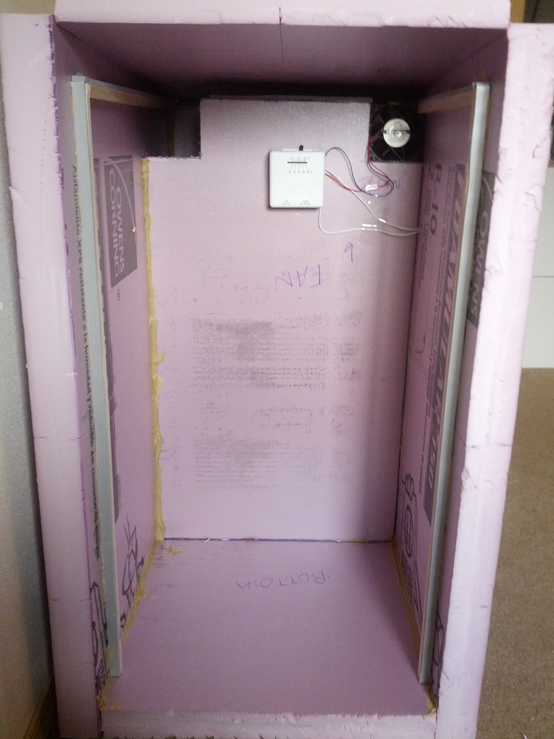
Finally I put the weatherstripping on the molding and cut the molding to the correct sizes so that it would run up the front and along both sides at the top. I glued these on with the liquid nails. The front modling inset 2 inches and the top molding was down 2 inches from the top. I put some more weatherstripping on the top of the rear panel, baffel, and “fan center” piece. This is to give it a better seal when the front and top panels are in place. Some people have installed rods in the top sides after pushing the top down to keep a more solid, air-tight box. I may do this, but in the interim just plan on putting something heavy on top of the lid.
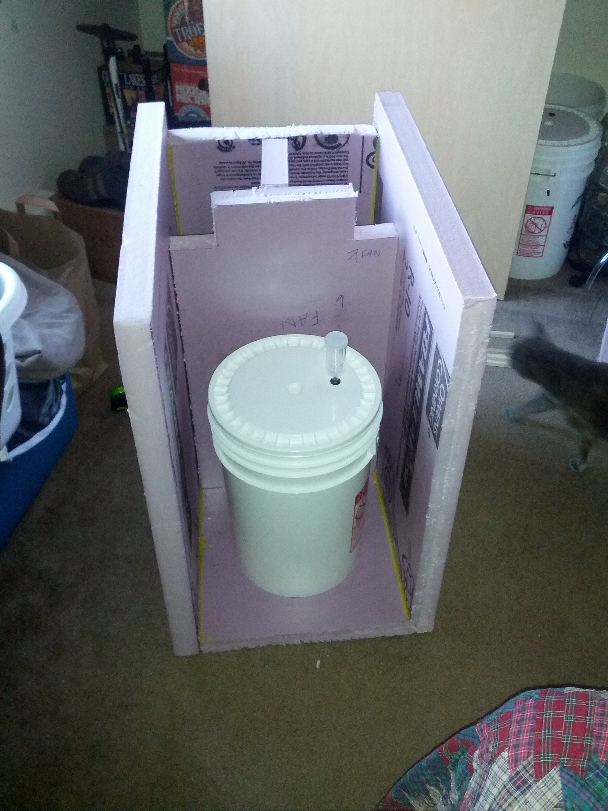
So, there you go! A “Son of a Fermentation Chamber”! I haven’t tested it out yet, as I need to freeze some jugs, but it should work pretty good. I should be brewing an Imperial IPA soon, so it will be the first beer to get proper temperature treatment. Take a look at the gallery below to see even more photos of the build process.
Photo Gallery


Tags: Build, Fermentation Chamber